
We have compiled most frequently asked .NET Interview Questions which will help you with different expertise levels.
.NET Interview Questions on UML, Estimation and Project Management
Note: We have released an exclusive book on ‘Architecture Interview questions’ which covers architectur
 in detail. Please e-mail bpb@boi.net.in for details.
Question 1.
Explain SOLID principles.
Answer:
SOLID (Single responsibility, Open-closed, Liskow substitution, Interface Segregation, and Dependency inversion) are five basic principles that help to create good software architecture. SOLID is an acronym where:
• S stands for SRP (Single Responsibility Principle): A class should take care of only one responsibility.
• O stands for OCP (Open Closed Principle): Extension should be preferred over modification.
• L stands for LSP (Liskov Substitution Principle): A parent class object should be able to refer child objects seamlessly during runtime polymorphism.
• I stands for ISP (Interface Segregation Principle): The client should not be forced to use an interface if it does not need it.
• D stands for DIP (Dependency Inversion Principle): High-level modules should not depend on low-level modules but should depend on abstraction.
Question 2.
What are design patterns?
Answer:
Design patterns are the recurring solutions to recurring problems in software architecture.
Question 3.
Which design patterns have you used in your project?
Answer:
This question is very subjective as every developer has his own experience. So we will pick up three design patterns, i.e., factory, singleton, and facade, and discuss the same in more depth. In case you are using some other design pattern below is the list with classification, go and pick your best three.
There are three basic classifications of patterns Creational, Structural, and Behavioral patterns.
Creational Patterns
- Abstract Factory: Create an instance of several families of classes
- Builder: Separates object construction from its representation
- Factory Method: Create an instance of several derived classes
- Prototype: A fully initialized instance to be copied or cloned
- Singleton: A class in which only a single instance can exist
Structural Patterns
- Adapter: Match interfaces of different classes.
- Bridge: Separates an object’s abstraction from its implementation.
- Composite: A tree structure of simple and composite objects.
- Decorator: Add responsibilities to objects dynamically.
- Facade: A single class that represents an entire subsystem.
- Flyweight: A fine-grained instance used for efficient sharing.
- Proxy: An object representing another object.
Behavioral Patterns
- Mediator: Defines simplified communication between classes.
- Memento: Capture and restore an object’s internal state.
- Interpreter: A way to include language elements in a program.
- Iterator: Sequentially access the elements of a collection.
- Chain of Resp: A way of passing a request between a chain of objects.
- Command: Encapsulate a command request as an object.
- State: Alter an object’s behavior when its state changes.
- Strategy: Encapsulate an algorithm inside a class.
- Observer: A way of notifying change to a number of classes.
- Template Method: Defer the exact steps of an algorithm to a subclass.
- Visitor: Define a new operation to a class without change.
Question 4.
What’s the first step you take for implementing any of the Design Patterns?
Answer:
Note: In this question the interviewer expects you to give a logical and practical answer. He is trying to
 understand have you really got the concept of design pattern.
Every design pattern solves certain problems. At the end of the day, they are tried and test solutions for a certain architecture problem. So you first need to understand what the problem is and then choose a design pattern accordingly. For instance below are some scenarios where the thought will flow as follows. ,
Problem: You want to create a single instance of an object.
Solution: Singleton design pattern.
Problem: Want to change the behavior of the class without altering the class.
Solution: Decorator pattern.
Problem: Want to loop through a collection without giving him modify access to the collection.
Solution: Iterator pattern.
Question 5.
Can you explain the factory pattern?
Answer:
Factory pattern is one of the types of creational patterns. You can make out from the name factory itself it’s meant to construct and create something. In the software architecture world, factory pattern is meant to centralize the creation of objects. Below is a code snippet of a client which has different types of invoices. These invoices are created depending on the invoice type specified by the client (See Figure 14.1). There are two issues with the code below:
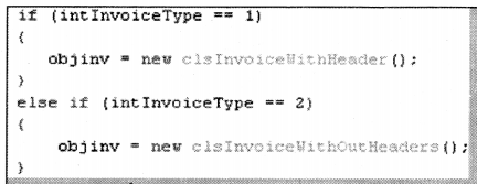
- First, we have lots of ‘new’ keywords scattered in the client, in other ways the client is loaded with a lot of object creational activities which can make the client logic very complicated.
- The second issue is that the client needs to be aware of all types of invoices. So if we are adding one more invoice class type called ‘InvoiceWithFooter’ we need to reference the new class in the client and recompile the client also.
Taking these issues as our base we will now look into how factory patterns can help us solve the same. Figure 14.2 ‘Factory Pattern’ shows two concrete classes ‘ClsinvoicewithHeader’ and ‘ClsInvoiceWithOutHeader’.
The first issue was that these classes are in direct contact with clients which leads to a lot of ‘new’ keywords scattered in the client code. This is removed by introducing a new class ‘ ClsFactoryinvoice’ which does all the creation of objects.
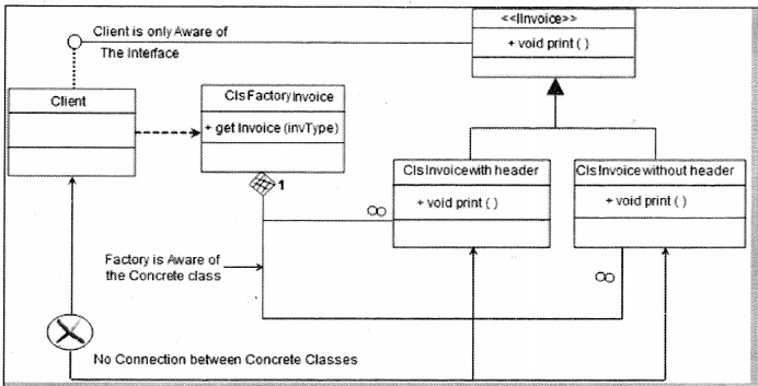
The second issue was that the client code is aware of both the concrete classes i.e. ‘ClsinvoicewithHeader’ and ‘ClsInvoiceWithOutHeader’. This leads to recompiling of the client code when we add new invoice types. For instance, if we add ‘ClslnvoiceWithFooter’ client code needs to be changed and recompiled accordingly. To remove this issue we have introduced
a common interface ‘Unvoice’. Both the concrete classes ‘ClslnvoiceWithHeader’ and ‘ CisinvoicewithOutHeader’ inherit and implement the ‘Unvoice’ interface.
The client references only the ‘ unvoice’ interface which results in zero connection between the client and the concrete classes (‘ClslnvoiceWithHeader’ and ‘ CisinvoicewithOutHeader’). So now if we add a new concrete invoice class we do not need to change anything on the client side.
in one line the creation of objects is taken care of by ‘cisFactoryinvoice’ and the client disconnection from the concrete classes is taken care of by the ‘ unvoice’ interface.
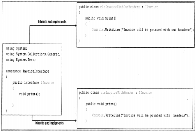
Below are the code snippets of how the actual factory pattern can be implemented in C#. In order to avoid recompiling the client, we have introduced the invoice interface ‘ unvoice’. Both the concrete classes ‘ClslnvoiceWithOutHeaders ‘ and ‘ClslnvoiceWithHeader’ inherit and implement the ’Unvoice’ interface.
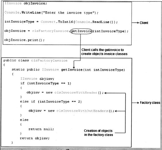
We have also introduced an extra class ‘ CisFactoryinvoice’ with the function ‘ get invoice () ‘ which will generate objects of both the invoices depending on the ‘ intinvoiceType’ value. In short, we have centralized the logic of object creation in the ‘ CisFactoryinvoice’. The client calls the ‘getinvoice’ function to generate the invoice classes. One of the most important points to be noted is that client only refers to ‘ unvoice’ type and the factory class ‘ CisFactoryinvoice’ also gives the same type of reference (See Figure 14.4). This helps the client to be complete detached from the concrete classes, so now when we add new classes and invoice types we do not need to recompile the client.
Question 6.
Can you explain the singleton pattern?
Answer:
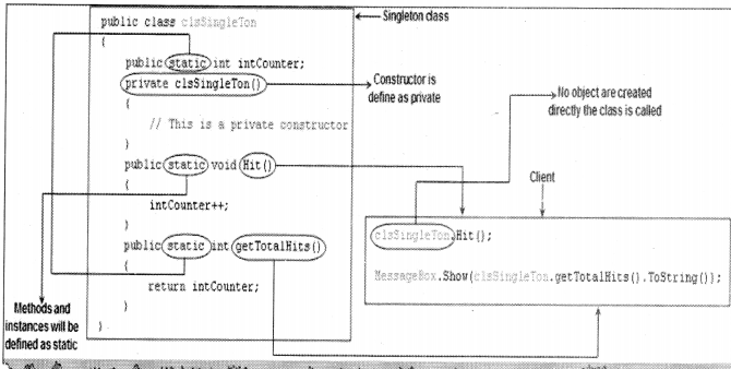
There are situations in a project where we want only one instance of the object to be created and shared between the clients. No client can create an instance of the object from outside. There is only one instance of the class which is shared across the clients. Below are the steps to make a singleton pattern:
- Define the constructor as private.
- Define the instances and methods as static.
Below is a code snippet of a singleton in C#. We have defined the constructor as private, defined all the instances and methods using the static keyword as shown in Figure 14.5. The static keyword ensures that only one instance of the object is created and you can all the methods of the class without creating the object. As we have made the constructor private, we need to call the class directly.
Question 7.
Can you explain the Facade pattern?
Answer:
The facade pattern sits on the top of the group of subsystems and allows them to communicate in a unified manner (See Figure 14.6).
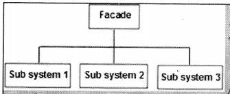
Figure 14.7 shows a practical implementation of the same. In order to place an order, we need to interact with product, payment, and invoice classes. So order becomes a facade that unites product, payment, and invoice classes.
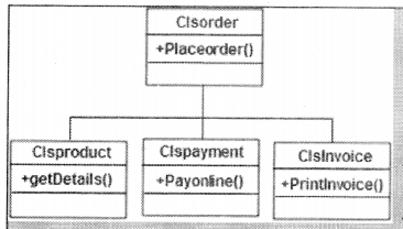
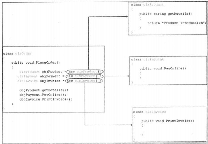
Figure 14.8 shows how class ‘clsOrder’ unifies / uses ‘ clsProduct’, ‘clsProduct’ and 1 clslnvoice’ to implement ‘PlaceOrder’ functionality.
Question 8.
What is the difference between Dl and loC?
Answer:
The main goal of Inversion of control and Dependency Injection (Dl) is to remove dependencies of an application. This makes the system more decoupled and maintainable.
First, let’s try to understand IOC (Inversion Of Control). If you go back to old computer programming days, program flow used to run in its own control. For instance, let’s consider a simple chat application flow as shown in the Figure 14.9 flow diagram.
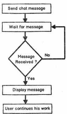
- End-user sends a chat message.
- The application waits for the message from the other end.
- If no message is found it goes to Step 2 or else moves to Step 4.
- Displays the message.
- The user continues with his/her work ahead.
Now if you analyze the program flow closely, it is sequential. The program is in control of itself, inversion of control means the program delegates control to someone else who will drive the flow. For instance, if we make the chat application event-based then the flow of the program will go something as below:
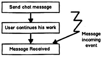
- End-user sends chat messages (See Figure 14.10).
- The user continues with his work ahead.
- The application listens to events. If a message arrives event is activated and the message is received and displayed.
If you see the program flow it is not sequential, it is event-based. So now the control is inverted. So rather than the internal program controlling the flow, events drive the program flow. The event flow approach is more flexible as their no direct invocation which leads to more flexibility
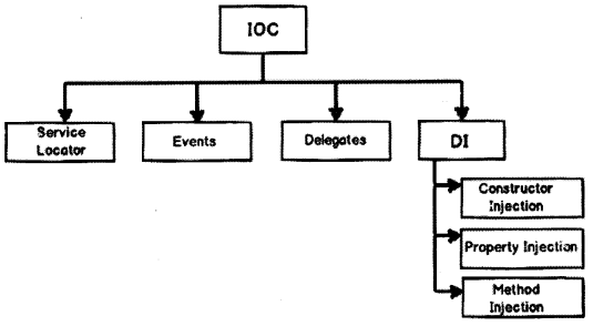
A word of caution here, do not conclude that loC are implemented by only events. You can delegate the control flow by callback delegates, observer pattern, events, Dl (Dependency Injection), and a lot of other ways.
loC (Inversion of Control) is a general parent term while Dl (Dependency Injection) is a subset of loC. C is a concept where the flow of the application is inverted. So for example rather than the caller calling the method.
SomeObj ect.Call( );
Will get replaced with an event-based approach as shown below.
SomeObject.WhenEvent += Call( );
In the above code, the caller is exposing an event, and when that event occurs he/she is taking action. It’s based on the Hollywood principle “Don’t call us we will call you”. In Hollywood when artists used to give auditions the judges would say to them “Don’t call us we will call you”.
The above approach makes code more flexible as the caller is not aware of the object methods and the object is not aware of caller program flow.
Dl provides objects that an object needs. So rather than the dependencies construct themselves they are injected by some external means. For instance, let’s say we have the class “Customer” who uses a “Logger” class to log errors as shown in Figure 14.2. So rather than creating the “Logger” from within the class, you can inject the same via a constructor as shown in the below code snippet.
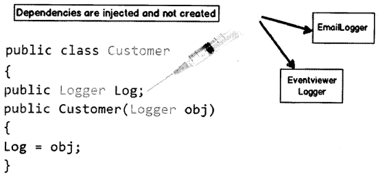
The biggest benefit achieved by the above approach is “Decoupling”. You can now invoke the customer object and pass any kind of “Logger” object as shown in the below code.
Customer obj = new Customer(new EmailLogger());
Customer obj1 = new Customer(new EventViewerLogger());
| Inversion of control | Dependency injection |
| It is a generic term and implemented in several ways (events, delegates, etc.) | Di is a subtype of loC and is implemented by constructor injection, setter injection, or method injection. |
Question 9.
What are MVC, MVP, and MWM patterns?
Answer:
All the above design patterns come in the presentation pattern category and help to remove any kind of cluttered code in Ul like manipulation of user interfaces and maintaining state. Thus keeping your Ul code cleaner and better to maintain.
Question 10.
What is the MVC pattern?
Answer:
The main purpose of using the MVC (Model View Controller) pattern is to decouple the GUI (Graphics User Interface) from the Data. It also gives the ability to provide multiple views for the same Data. MVC pattern separates objects into three important sections:
• Model: This section is especially for maintaining data. It is actually where your business logic, querying database, database connection, etc., is actually implemented.
• Views: Displaying all or some portion of data, or a probably different view of data. The view is responsible for look and feel, sorting, formatting, etc.
• Controller: They are event-handling section, which affects either the model or the view. The controller responds to the mouse or keyboard input to command model and view to change. Controllers are associated with views. User interaction triggers the events to change the model, which in turn calls some methods of model to update its state to notify other registered views to refresh their display.
Question 11.
How can we implement MVC in ASP.NET?
Answer:
By using theASP.NET template provided in Visual Studio.
Question 12.
What is MVP?
Answer:
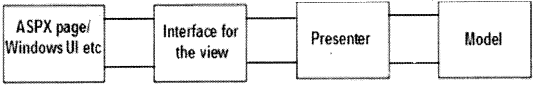
MVP (Model View Presenter) has the same goals as MVC, i.e., separating the III from the model. It does the same by using a presenter class. The Ul talks via an interface to the presenter class and the presenter class talks with the model.
The presenter class contains all the code needed for model communication and synchronization.
Question 13.
What is MWM?
Answer:
Again MWM is an architectural pattern with the focus of removing Ul cluttered code. It does the same by using an extra class called a view model. MWM is mostly suitable for Silverlight and WPF projects because of the rich bindings provided by the technologies.
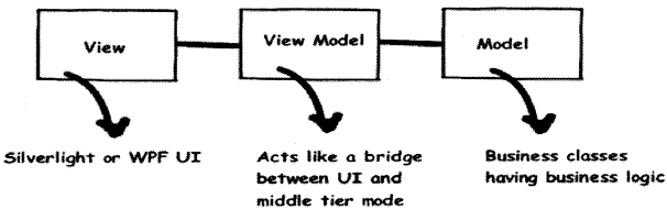
So Ul talks with the view model class and the view model class interact with the model class.
Question 14.
What is the difference between MVC, MVP, and MWM, and when to use what?
Answer:
MVC: Here the first hit comes to the controller and the controller ties up the view and model and sends the same to the user.
MVP: Here the first hit comes to the Ul and the Ul interacts with a presenter class who talks with the model.
MWM (Model-View-View-Model): here the first hit comes to Ul and Ul talks to the model via a separate class called a view model. Rich bindings are used by the view model class to communicate to the model thus keeping the Ul code clean.
MVC is good for Web applications like ASP.NET, MVP for windows applications, and MWM for Silverlight and WPF projects as they have rich bindings.
Question 15.
What is three-tier architecture?
Answer:
The three-tier software architecture emerged in the 1990s to overcome the limitations of the two-tier architecture.
Question 16.
There are three layers when we talk about three-tier architecture:
Answer:
User Interface (Client): This is mostly the windows user interface or the Web interface but this has only the Ul part.
Mid-layer: Middle tier provides process management where business logic and rules are executed and can accommodate hundreds of users (as compared to only 100 users with the two-tier architecture) by providing functions such as queuing, application execution, and database staging.
Data Access Layer: This is also termed by the famous acronym “DAL” component. It has mainly the SQL statement which do the database operation part of the job.
Question 17.
Have you ever worked with Microsoft Application Blocks, if yes then which?
Answer:
Application Blocks are C# and VB.NET classes distributed as Visual Studio projects that can be downloaded from Microsoft’s Website and used in any .NET application, including ASP.NET Web applications. They are useful and powerful tools that can make applications more maintainable, scalable, and efficient
Secondly, which application blocks have been used depends on really what you have implemented. However, there are two famous MABs, which is making buzz around the industry:
Data access block: Data access block gives us a readymade DAL component.
Exception management block: This block gives us reusable classes which can reduce exception handling in the project.
Question 18.
What is service-oriented architecture?
Answer:
“Services” are components, which expose well-defined interfaces, and these interfaces communicate through XML messages. Using SOA (Service Oriented Architecture), you can build a workflow, which uses interfaces of these components. SOA is typically useful when you are crossing heterogeneous technical boundaries, organizations, domains, etc.
In .NET, SOA technically uses Web services to communicate with each service, which is crossing boundaries. You can look at SOA, which sits on top of Web services and provides a workflow.
SOA uses service components, which operate in their own domain boundary. Let us note some points of service:
- They are independent components and operate in their own boundary and own technology.
- They have well-defined interfaces, which use XML and WSDL (Web Services Description Language) to describe themselves.
- Services have URLs where anyone can find them and clients can bind to these URLs to avail of the service.
- Services have a very loosely coupled architecture. In order to communicate to service you only have to know the WSDL (Web Services Description Language). Your client can then generate a proxy from the WSDL of the service.
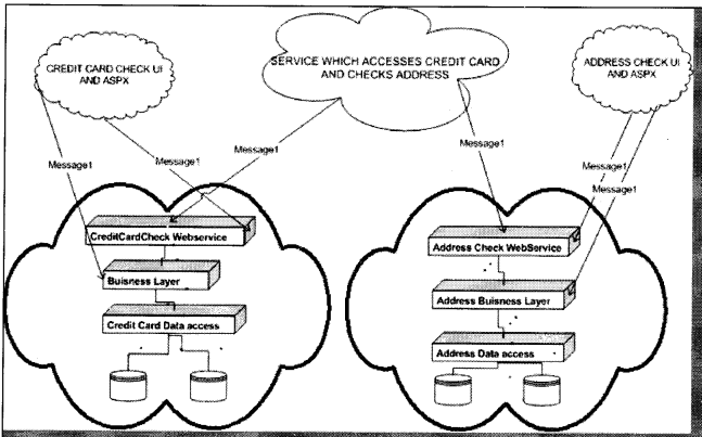
Figure 14.15 describes a broader picture of what service-oriented architecture will look like. The fundamental of SOA is a Web service. In the above diagram, you can see there are two services available. One is the “Credit Card” service and the other is the “Address Check” Web service.
Both these services are provided by a different company. Now we want to build functionality, which needs to validate a credit card and check that addresses are proper. In short, we will need functionalities of both the “Credit Card” and “Address Check” services. Also, note the “Credit Card” service has its own business layer and DAL components, which can be in a proprietary language.
It is very much possible that the whole Credit card service is made in .NET and the Address check is SAP (Systems, Application, and Products) implementation or Java implementation. However, because both the systems provide their functionality using Web services which is nothing but XML message communication. So we have made a new service that sits like a FAQADE on top of both the Web service and performs both functionalities in one common service. You will see I have made a third service which sits on top of both the Web service and consumes them. Also, you can see that the Ul part of the systems has access to the Business layer and Web service of their system. However, the service which does both these checks has only access to the Web service.
Note: It’s beyond the scope of this book to discuss SOA. However, just to keep you safe during the interview this book has tried to clear some basics of SOA. I will really stress you to read the WCF chapter of this book, which talks in detail about how Microsoft has visualized SOA.
Question 19.
What are different ways you can pass data between tiers?
Answer:
There are many ways you can pass data between tiers:
- Dataset is the most preferred one as they maintain data in XML format.
- Data reader
- Custom classes.
- XML
Question 20.
What is UML?
Answer:
The Unified Modeling Language (UML) is a graphical language for visualizing, specifying, constructing, and documenting the artifacts of a software-intensive system. UML provides blueprints for business processes, System functions, programming language statements, database schemas, and reusable components.
Question 21.
How many types of diagrams are there in UML?
Answer:
There are nine types of diagrams in UML:
Use case diagram: They describe the “WHAT” of a system rather than “HOW” the system does it. They are used to identify the primary elements and processes that form the system. The primary elements are termed as “actors” and the processes are called “use cases”. Use Case diagrams show “actors” and their “roles”.
Class diagram: From the use case diagram, we can now go to the detailed design of system, for which the primary step is class diagram. The best way to identify classes is to consider all “NOUNS” in use cases as classes, “VERBS” as methods of classes, relation between actors can then be used to define the relation between classes. The relationship or association between the classes can be either an “is-a” or “has-a” relationship which can easily be identified from use cases.
Object diagram: An object is an instance of a class. Object diagram captures the state of classes in the system and their relationships or associations at a specific point of time.
State diagram: A state diagram, as the name suggests, represents the different states that objects in the system undergo during their life cycle. Object change in response to certain simulation so this simulation effect is captured in state diagram. Therefore, it has an initial state and final state and events that happen in between them. Whenever you think that some simulations are complicated, you can go for this diagram.
Sequence diagram: Sequence diagrams can be used to explore the logic of a complex operation, function, or procedure. They are called sequence diagrams because sequential nature is shown via ordering of messages. First message starts at the top and the last message ends at bottom. The important aspect of a sequence diagram is that it is time-ordered. This means that the exact sequence of the interactions between the objects is represented step-by-step. Different objects in the sequence diagram interact with each other by passing “messages”.
Collaboration diagram: A collaboration diagram groups together the interactions between different objects to fulfil a common purpose.
Activity diagram: Activity diagram is typically used for business process modeling, for modeling the logic captured by a single use case, or for visualizing the detailed logic of a business rule. Complicated process flows in the system are captured in the activity diagram. Similar to a state diagram, an activity diagram also consists of activities, actions, transitions, initial and final states, and guard conditions. However, difference is state diagrams are in the context of simulation while activity gives a detailed view of business logic.
Deployment diagram: Deployment diagrams show the hardware for your system, the software that is installed on that hardware, and the middleware used to connect the disparate machines to one another. It shows how the hardware and software work together to run a system. In one, line its shows the deployment view of the system.
Component diagram: The component diagram represents the high-level parts that make up the system. From the .NET angle point of view, they form the “NAMESPACES”. This diagram depicts, at a high level, what components form part of the system, and how they are interrelated. Its shows the logical grouping of classes or group of other components.
Note: The best way to remember all the blocks of UML is “Serve cool SOUP during church ceremony” that covers
State chart, Class diagrams, Sequence diagram, Object diagram, Use Case diagram, Package diagram, Deployment
diagram, Collaboration diagram, Component diagram.
Question 22.
What are the advantages of using UML?
Answer:
Modeling has been around for years, not only in software field but also in other trades like civil, mechanical etc. For example in civil engineering drawing the main architecture built of the diagram is a model by itself. Modeling makes complex and huge system to break up into simple and discrete pieces that can be individually understood. Example simple flowchart drawing is modeling.
There are two main advantages of modeling:
- Readability: Representing your whole architecture in flowchart, class diagrams, ER (Entity Relationship) diagrams, etc., makes your project more readable. Especially when programmer’s change jobs handover becomes easier. More the project is not readable more the dependencies.
- Reusability: After the system is more readable and broken down into pieces, it becomes easier to identify redundant and similar modules. Thus increasing reusability.
So why UML? Well, different languages have different ways of coding and syntaxes. In order to bring all languages in one roof UML is in to picture. As the term comes in Unified, it unifies all disparate languages in one roof so people who are working on some other platforms can understand that.
Question 23.
How did you implement UML in your project?
Answer:
First, let me say, some fact about this question, you cannot implement all the nine diagrams given by UML in one project; you can but can be the very rare scenario. The way UML is implemented in project varies from project to project and company to company.
A second very important point to remember is normally all diagrams are not implemented in a project, but some basic diagrams are important to have in order for the project to be readable. When we talk about projects every project has phases example (Requirements phase, the design phase, the coding phase, etc.). As every phase of the software cycle proceeds, these diagrams come into the picture. Some diagrams span across multiple phases.
Note: If you want to have a detail about software life cycle look out for chapter “Project Management”.
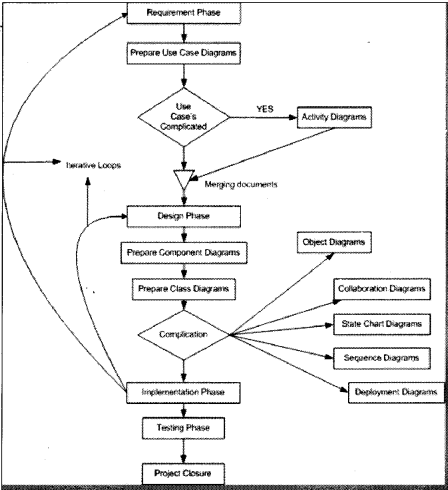
Normally following are different basic phases:
Requirement phase (Use Case Diagrams, Activity diagrams)
The requirement phase is the phase where you normally gather requirements and use cases are the best things to make the explanation of the system. In requirement phase, you can further make complicated use cases more simple and easy to understand by using activity diagrams, but I do not see it as a must in every project. If the use cases are complicated, go for a Activity diagram. Example CRUD (Create, Read, Update and Delete) operation use cases have no significance for making activity diagrams. So in short, the outcome UML documents from requirement phase will be use case and Activity diagram documents (Activity diagram documents will only be there if there are complicated use cases to be simplified).
Note: This question is specially asked to know have you actually used UML. I have seen many guys trying to
give some jack of all answers saying “YES”. Beware it is a trap.
Not all diagrams are needed in project example: Activity diagrams will only be needed when you want some simplified look of a complicated use case.
Design phase (Class diagrams, object diagrams, Component diagrams, Collaboration diagrams, Deployment diagrams, Sequence diagrams)
Design phase is the phase where you design your technical architecture of your project. Now again in this you do not use all UML documents of a project.
However, the next document after the use case document will be the Component diagram. Component diagrams form a high-level classification of the system. So after “Use Cases” just try to come out with a high-level classification / grouping of related functionalities. This should be compulsory diagram, as outcome of this document will form “NAMESPACES” structure of .NET project.
Ok now once your high-level grouping is done you can go ahead with class diagrams. Especially from Use Case you get the “NOUNS” and “VERBS” which can form the class name and the method name respectively. From my point of view, class diagrams should be compulsory in projects.
Object diagrams are not compulsory it depends on how complicated your project. Object diagrams show the relation between instances of class at runtime. In short, it captures the state and relation of classes at any given moment of time. Example you have class which creates objects of different classes, its like a factory. In class diagram, you will only show that it as a simple class with a method called as “Create Object”. However, in object diagrams actually you will show the types of instances create from that object.
Collaboration diagrams mainly depict interaction between object to depict some purpose. I find this diagram to be more useful than Object diagrams as they are addressed for some purpose example “Login Process” which will use “Login object”, “User Object”, etc., to fulfill the login purpose. Therefore, if you find the process very complicated go for this diagram. I see as a thumb rule if there is an activity diagram, which shows some serious complicated scenarios. I will like to go for this diagram in order to simplify the explanation.
State chart diagram is again created if your project requires it. If your project has some complicated start and end states to show then this diagram is most useful. Recently I was making a call center project where the agent phone pickup and hang state has to be depicted. So my first state was when agent picks up the phone and the final stage was when agent hangs the phone, in between process was very complicated, which can only be shown by using state chart diagrams.
Sequence diagrams are needed if some sequence is complicated. Do not confuse sequence diagrams with Activity diagram, Activity diagrams map to a use case while sequence diagrams show object interaction in sequence.
Deployment diagrams are again not a compulsory requirement. It will show the hardware and software deployment of your system. If you really have leisure in your project go for it or if you want to make the client smile seeing some diagrams.
Implementation phase / Coding phase (Class diagrams for reverse Engineering, other diagrams for validity check)
In this phase, mostly class diagrams are re-engineered with the source code. However, other diagrams are also present for validity check example state chart diagrams will be used in case to check that the both activity between those states follow the proper logic. If some things have to be changed, then again there is iteration backward to the Requirement phase.
Testing phase
This phase mostly goes for the testing department. I am not talking about preparing UTP (Unit Test Plans) but SITP (System Integration Test Plans). Where the testing department will look at all diagrams to prepare a test plan and execute it. For example it will see the use case document to see the business rules, it will see the activity diagram and sequence diagrams to see the proper flow of modules. If some things are not proper, there is iteration back to the Design phase.
Roll out and close over phases.
All documents just to re-check that things are proper, for example, all modules deployed according to the deployment diagrams, are all business rules in use cases satisfied.
Let us revise the following points:
- Not all diagrams are compulsory.
- The minimum diagrams according to software life cycle phases are:
- Requirement phase: Use case diagrams o Design Phase: Component diagrams, class diagrams
- Implementation phase: All diagrams derived from pervious phases specially class diagram for reverse engineering.
- Testing phase: All diagrams derived from requirement and design phases for verification and preparing test plans.
- Roll out and close over phase: All document derived from Design phase and requirement phases.
Figure 14.16 shows all the documents in relevant phases.
Note: This book will now attempt to describe every element of a UML diagram. But it is advisable that you
 should install any decent UML tool and do a small practice of one or two diagrams which will make you comfortable
during the interview.
Question 24.
What are the different phases in a software life cycle?
Answer:
There are six phases in software development:
- Requirement
- Design
- Coding and unit testing
- System testing
- Acceptance testing
- Go live
Question 25.
Can you explain different software development life cycles?
Answer:
SDLC (System Development Life Cycle) is the overall process of developing information systems through multi-stage process systems from the investigation of initial requirements through analysis, design, implementation, and maintenance. The days are gone when one COBOL (Common Business Oriented Language) programmer used to analyze, test, and implement software systems. Systems have become complex, huge team members are involved, architects, analysts, programmers, testers, users, etc. To manage this number of SDLC models have been created.
Following are popular models, which are listed:
- Waterfall Model
- Spiral Model
- Build and Fix model
- Rapid prototyping Model
- Incremental Model
Let discuss each of the SDLC models in brief.
Water Fall Model
This is the oldest model. It has a sequence of stages; the output of one stage becomes the input of the other. Following are stages in the Waterfall model:
• System Requirement: This is the initial stage of the project where end-user requirements are gathered and documented.
• System Design: In this stage detailed requirements, screen layout, business rules, process diagram, pseudo code, and other documentation are prepared. This is the first step in the technical phase.
• Implementation: Depending on the design document, actual code is written here.
• Integration and Testing: All pieces are brought together and tested. Bugs are removed in this phase.
• Acceptance, Installation, and Deployment: This is the final stage where software is put in production and runs actual business.
• Maintenance: This is the least glamorous phase, which runs forever. Code Changes, correction, addition, etc., are done in this phase.
The waterfall is suited for low risk in areas of User Interface and performance requirements, but the high risk in budget and schedule predictability and control. Waterfall assumes that all requirements can be specified in advance. But unfortunately, requirement grows and changes through various stages, so it needs feedback from one stage to other.
Spiral Model
Spiral Model removes the drawback of the waterfall model, by providing emphasis to go back and reiterate earlier stages a number of times as the project progresses. On a broader level, it is a series of short waterfall cycles, each producing an early prototype representing a part of the entire project. It also helps demonstrate a Proof of Concept in the early software life cycle.
Build and Fix Model
This is the way free-lancers work write some code and keep modifying it until the customer is happy. This approach can be quite dangerous and risky.
Rapid Prototyping Model
This model is also called Rapid Application Development (RAD). The initial emphasis is on creating a prototype that looks and acts like the desired product. The prototype can be created by using tools, which are different from those used for the final product. Once the prototype is approved, it’s discarded and real software development is started from scratch. The problem with this model is that sometimes the prototype moves ahead to become the final live product, which can be bad from the design point of view. It is an effective model but can have higher costing than other models as you require programmers during the initial phase of the software cycle.
Incremental Model
In this model, we divide products into builds, where sections of products are created and tested separately. Here errors are found in the requirement phase itself, user feedback is taken for each stage, and code is tested after it is written.
Question 25.
What does Agile mean?
Answer:
Dictionary meaning of Agile is quick moving. Now how does that apply to software? Agile development methodology considers software as the most important entity and accepts user requirement changes. Agile advocates that we should accept changes and deliver the same in small releases. Agile accepts change as a norm and encourages constant feedback from the end-user.
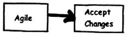
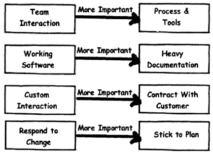
The below figure shows how Agile differs in principles from traditional methodologies.
- It’s not necessary to have hi-fi tools and processes but a good team interaction can solve a lot of problems.
- Working software is more important than documentation.
- Management should not pay attention to only customer contracts rather interact with customers and analyze the requirements.
- \n trarMonat methodologies we pledge to stock. our plans but age says the customer wants to change, analyze and change your plan accordingly”.
Below are principles of Agile methodology:
- Welcome change and adapt to changing requirements
- Working software is the main measure of progress.
- Customer satisfaction is the most important thing and that can be attained by rapid, continuous delivery of useful software
- Day-to-day meetings between business people and the development team is a must.
- Businesses and developers must work together. Face to face to communication is the most important thing.
- Deliver and update software regularly. In Agile we do not deliver software in one go, but rather we deliver frequently and deliver the important features first.
- Build projects around teams of motivated and trustful people.
- Design and execution should be kept simple.
- Strive for technical excellence in design and execution.
- Allow the team to organize themselves.
Question 26.
What is Scrum?
Answer:
SCRUM is a methodology which believes rapid changes of customers cannot be solved by the traditional approach. So it adopts an empirical approach where it believes the problem can not be understood or defined. Rather concentrate on the team’s ability to respond to the emerging requirements.
Question 27.
What do product owner, product backlog, and sprint mean in Scrum?
Answer:
Before we understand the SCRUM cycle let’s get familiar with some terms regarding SCRUM.
The Product Owner is the end customer or the user.
A product backlog is a list of prioritized items to be developed for a software project.
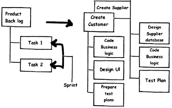
Sprint is the task breakup of a product catalog. It’s the detailed task breakdown for a development team.
Figure 14.19 shows a typical product catalog broken into sprints. On the left-hand side of Figure 14.19, we have shown two items in the product backlog “Create Customer” and “Create Supplier”. To complete “Create Customer” the developer need to the following sprint task “Code Business Logic”, “Design Ul” and “Prepare Test Plans”.
Question 28.
Can you explain how Scrum flows?
Answer:
Figure 14.20 shows how the development flow moves in a project. We will understand the SCRUM flow step-by-step.
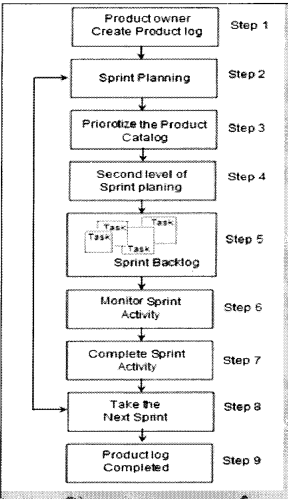
Step 1: The product owner (i.e., the customer) creates a list of product logs (list of functionalities).
Steps 2 and 3: In these phases, we sit with the customer and prioritize the product catalog. We discuss with the customer which functionality is a must and must be delivered first.
Steps 4 and 5: In both these phases we break down the product catalog into tasks called sprint backlog.
Step 6: We start executing the sprint task and monitoring the sprint activity.
Steps 7 and 8: Once we are done with the sprint activity, we take the next sprint/task by again going to the sprint phase.
Step 9: If there are no more sprints/tasks the product log is completed, which means the project is completed.
Question 29.
Can you explain the different roles in SCRUM?
Answer:
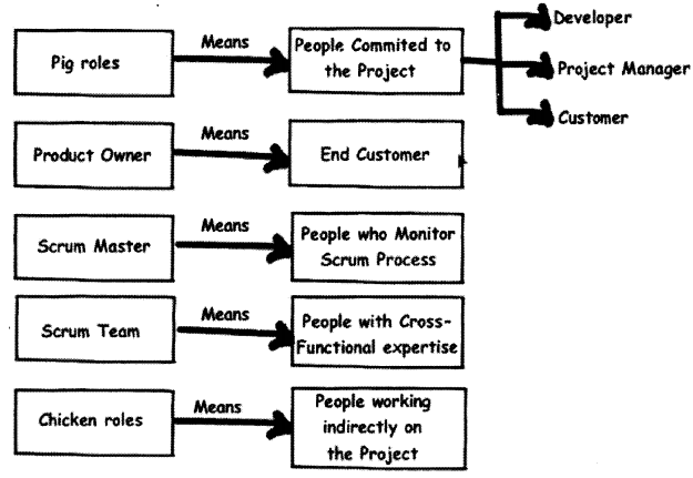
Scrum has some different terminologies when it comes to role names in Scrum (See Figure 14.21). Below is the list of roles with what actually they mean.
People with pig roles are those people who are committed to the project. If the project fails it affects these people. So of the big roles are developer, customer, project manager, etc.
Product owner means the end customer or user.
Scrum master is the process driver. These are the people who drive the scrum process. They are consultants for the Scrum process.
People with chicken roles work indirectly on the project. They do not really benefit from the project but their feedback is valuable to the project. They cannot be held responsible if the project is not successful.
Question 30.
When should we choose Agile and when should we choose waterfall?
Answer:
Agile is the best choice when your requirements are evolving and not fixed. If your requirements are fixed waterfall becomes a better choice.
Question 31.
What are some of the important metrics in the project?
Answer:
There are different kinds of metrics but there are three prime metrics planned value, earned value, and actual cost. These three metrics help us to understand where the project stands today.
Question 32.
What is effort variance?
Answer:
Effort Variance = (Actual effort – Estimated Effort) / Estimated Effort.
Question 33.
What is CAR (Causal Analysis and Resolution)?
Answer:
The basic purpose of CAR is to analyze all defects, problems, and good practices/positive triggers in projects, perform a root cause analysis of the same, identify respective corrective and preventive actions, and track these to closure. The advantage of CAR is that root causes are scientifically identified and
their corrective and preventive actions are carried out. CAR needs to be performed at project initiation, all phases and project ends, and on a monthly basis. A Fishbone diagram is one of the ways you can do CAR.
Question 34.
What is DAR (Decision Analysis and Resolution)?
Answer:
Decision Analysis and Resolution is to analyze possible decisions using a formal evaluation process that identifies alternatives against established criteria.
For example, in a project, you are said to use third-party tools so you will not depend on only one tool but evaluate three to four more tools so that in case of problems you have alternatives. This is called as DAR.
Question 35.
What is a fishbone diagram?
Answer:
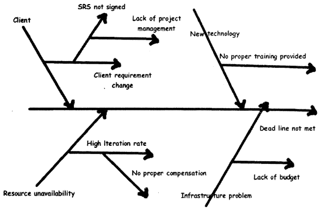
Dr. Kaoru Ishikawa invented the fishbone diagram. Therefore, it can be also referred to as the Ishikawa diagram.A Fishbone diagram is an analysis diagram, which provides a systematic way of looking at effects and the causes that create or contribute to those effects. Because of the function of the fishbone diagram, it may be referred to as a cause-and-effect diagram. The design of the diagram looks much like the skeleton of a fish. Therefore, it is often referred to as the fishbone diagram.
Fishbone diagram helps in categorizing potential causes of problems or issues in an orderly way and in identifying root causes.
Figure 14.22 shows a sample of fishbone diagram, which illustrates why a project deadline was not met. The middle arrow is the main problem “Deadline not met”. Then we start analyzing other problems, which have led to this problem. For example, there is client problem — as he/she is always changing the requirement — this is caused because the company did not sign the SRS (Software Requirements Specification) — and this happened as proper project management procedures where not at place. So to solve this problem we either appoint a project manager or give training on project management to senior team members.
Question 36.
What is Pareto principle?
Answer:
Pareto principle also paraphrased as 80/20 principle is simple effective problem tackling way in management. It says that 20% of your problems lead to other 80 % of problems. So rather than concentrating on the 80% of problem if you concentrate on 20% of problems you can save lot of trouble. So in pareto you analyze the problems and only concentrate on 20% of your vital problems. In projects, the first 10% and the last 10% of project form the vital part of project.
Question 37.
What are functional and non-functional requirements?
Answer:
Functional requirements defines “What” of the system while non-functional requirement define “How” of the system. Function requirements define business requirements while non-functional requirement define technical requirements.
Below is a simple example in both of them:
Functional: Display the report how much sales have been done this month.
Non-functional: The report should be displayed in 15 seconds.
Question 38.
How do you handle change request?
Answer:
Normally change requests are handled by preparing an Impact analysis document and then doing re¬estimation. Example you have an ongoing project, which has a customer table. Now customer wants to also have addresses assigned to it. Therefore, you normally raise a change request and then do an impact analysis of the same. Depending on the impact, you estimate and let know the client about the financial aspect of the project. Once client sign off or the upper management agrees to the change request you move ahead with implementation.
Question 39.
What is internal change request?
Answer:
Internal change request are not normally billable change request, it has no financial gains from the client. Example your architecture division of your company has said in mid of the project that the architecture has to be modified. Definitely this has nothing to do with the client, but you make changes to the project so this is called as Internal change request.
Question 40.
What is difference between SITP and UTP in testing?
Answer:
UTP (Unit Test Plan) are done at smallest unit level or stand-alone mode. Example you have Customer and invoicing module. So you will do test on Customer and invoice module independently. But later when we want test both customer and invoice in one set we integrate them and test it. So that’s is SITP (System Integration Test Plan)
UTP can be done using NUnit (an open source unit testing framework for Microsoft .NET). Unit testing is done normally by developers and System testing is done normally by testing department in integration mode.
Question 41.
Which software have you used for project management?
Answer:
Many companies have there own software defined. There are many project management software available at this moment in market but this can vary from company to company.
Worst it can vary from project to project. But Microsoft project is the most used software at this moment. So just brush your skills on Microsoft project, its used heavily across industry.
Question 42.
People in your project do not perform, what will you do?
Answer:
In such kind of question, they want to see your delegation skills. The best answer to this question is a job of a project manager is managing projects and not problems of people, so I will delegate this work to HR (Human Resource) or upper authority…. Thanks to my Project Manager for this beautiful answer.
Question 43.
What is black box testing and White box testing?
Answer:
Black box testing is also termed as functional testing. It ignores how the internal functionality of a system works and depends only what are the outputs on specified inputs. Source code availability is not an important in back box testing. Black box testing is mostly to ensure that it meets the user functionality.
According to IEEE (Institute of Electrical and Electronics Engineers), standards following are characteristics of Black box testing:
- “Testing that ignores the internal mechanism of a system or component and focuses solely on the outputs generated in response to selected inputs and execution conditions,”
- “Testing conducted to evaluate the compliance of a system or component with specified functional requirements.”
One of the way of doing black box testing is Manual testing what the tester performs. For instance, you can install the application on a machine and tester starts testing is a type of black box testing. In our case the tester is completely unaware of the how the program logic flows and how its coded, etc.
White box testing is opposite to Black box it requires internal know how of how the logic flows. As this testing needs know how of the internal structure it can only be done programmers. Unit testing is one of the ways of doing White box testing in which programmers use NUNIT or JUnit (a unit testing framework) to test each class individually. White box testing can be done by programmer by either stepping through the code or testing the classes and components in isolation.
Question 44.
What is the difference between Unit testing, Assembly testing and Regression testing?
Answer:
Unit testing is also termed as Component testing. This testing ensures that reliable program unit meets their requirements. Unit testing is normally conducted by programmer under the supervision of the project lead or the team Lead. Main objective of this testing is to test each unit in isolation and individually. This is done by knowing what the inputs to the unit are and what the expected outputs for the same. Unit testing is a white box activity. Unit test normally comes in the implementation phase of the project.
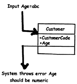
For instance in Figure 14.23, we are trying to do unit testing on the customer class. So we create the object of the Customer class assign “CustomerCode” and “Age” properties and check for the response. For instance, in this condition, we tried to pass a non-numeric value to the “Age” property and the class threw an error saying, “Age should be numeric”. So here the basic unit testing entity is your class.
However, unit testing is not limited to a component, object, or function. Therefore, the definition of unit testing will depend on the approach. Below are some examples of unit testing:
- Checkpoints in Ul (User Interface) like tab orders, error messages, look and feel, etc.
- Class, object, component-level testing as said previously. In the case of functional programming can be a simple method or function.
- Logic testing for algorithms. Some projects can have some critical algorithm for instance some kind of custom sorting, security implementation, etc. Therefore, that logic can be tested independently.
However, the general thumb rule of what is Unit in Unit testing is that the module is self-contained and by itself.
Assembly testing goes one step ahead of unit testing. It demonstrates that can the modules interact in a correct, stable, and proper manner as defined by the functional specifications provided by the client. Assembly testing is a Black box testing style and is also called Integration testing. For instance, in the above unit test of the “Customer” class, testing was done in isolation. But in actuality the “Customer” class is not going to be stand alone rather it will be used more in conjunction with the “Product” class and also will have Ul do the same. So in short, the “Customer” class will work with two more entities one is the “Ui” and the other is the “Product” class (See Figure 14.24). So normally, assembly testing is done through Ul but not necessarily.
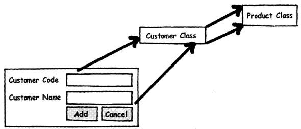
Figure 14.24 defines a simple scenario for integration testing. The same “Customer” class is now tested with the “Ul” and “Product” to see if the interaction between them matches according to functional specifications.
Regression testing ensures that applications function properly even if there are changes or enhancements to the system. For instance, you change the “Product” class still will run all the test cases for “Product”, “Customer” and “Ul” just to make sure that any changes in the “Product” class do not affect interaction with other entities. So you will see when testers do regression testing they run all the scripts to ensure that nothing has been affected.
Question 45.
What is V model in testing?
Answer:
V model maps the type of test to the stage of development in a project (See Figure 14.25). V model stressed the point that every phase in project should have a test phase also.
Unit Testing: Starting from the bottom the first test level is “Unit Testing”. It involves checking that each feature specified in the “Component Design” has been implemented in the component.
In theory, an independent tester should do this, but in practice, the developer usually does it, as they are the only people who understand how a component works. The problem with a component is that it performs only a small part of the functionality of a system, and it relies on co-operating with other parts of the system, which may not have been built yet. To overcome this, the developer either builds, or uses special software to trick the component into believe it is working in a fully functional system. This test maps with the implementation phase and normally developers do the unit testing for the project.
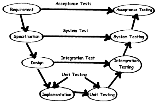
Integration Testing: As the components are constructed and tested they are then linked together to check if they work with each other. It is a fact that two components that have passed all their tests independently when connected to each other produce one new component full of faults. These tests can be done by specialists, or by the developers.
Integration Testing is not focused on what the components are doing but on how they communicate with each other, as specified in the “System Design”. The “System Design” defines relationships between components.
The tests are organized to check all the interfaces until all the components have been built and interfaced with each other producing the whole system. Integration test cases are written when design documents are written.
System Testing: Once the entire system has been built then it has to be tested against the “System Specification” to check if it delivers the features required. It is still developer-focused, although specialist developers known as systems testers are normally employed to do it.
In essence, system testing is not about checking the individual parts of the design, but about checking the system as a whole. In fact, it is one giant component.
System testing can involve a number of specialist types of tests to see if all the functional and non¬functional requirements have been met. In addition to functional requirements, these may include the following types of testing for the non-functional requirements:
- Performance – Are the performance criteria met?
- Volume – Can large volumes of information be handled?
- Stress – Can peak volumes of information be handled?
- Documentation – Is the documentation usable for the system?
- Robustness – Does the system remain stable under adverse circumstances?
There are many others, the need for which is dictated by how the system is supposed to perform. System test plans are written when the specification of the project is going on.
Acceptance Testing
Acceptance Testing checks the system against the “Requirements”. It is similar to systems testing in that the whole system is checked but the important difference is the change in focus:
Systems testing checks that the system that was specified has been delivered. Acceptance Testing checks that the system will deliver what was requested.
The customer should always do acceptance testing and not the developer. The customer knows what is required from the system to achieve value in the business and is the only person qualified to make that judgment. This testing is more of getting the answer for whether is the software delivered as defined by the customer. It is like getting a green flag from the customer that the software is up to the expectation and ready to be used. Acceptance test plans are written during the requirement phase of the project. In a real scenario, these test plans should be given by the end customer.
Question 46.
How do you start a project?
Answer:
Left to the readers.
Question 47.
How did you do resource allocations?
Answer:
Left to the readers.
Question 48.
How will you do code reviews?
Answer:
The way in which code reviews are done changes from person to person and also company to company.
However, normally when a project is started project people define their architecture, coding standards, etc., in their design document. So before starting the code review you will have to go through the standards defined in the project. Reviews are done by two methodologies one is peer review and the other is by the external party who is not a member of the project. So we give the standard document to the reviewer he checks it, gives his perspective, and logs a review to the development. If the review is critical then the development team can close it or they can wave it off.
Question 49.
What is CMMI?
Answer:
It is a collection of instructions an organization can follow with the purpose to gain better control over its software development process (See Figure 14.26).
Question 50.
What are the five levels in CMMI?
Answer:
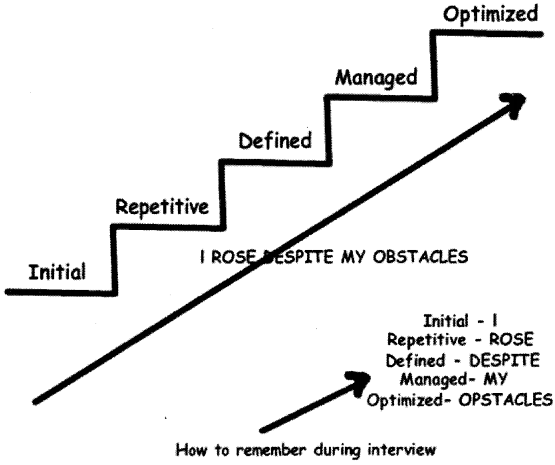
According to the SEI (Software Engineering Institute), there are five levels of the CMMI (Capability Maturity Model Integration).
Level 1 – Initial
At maturity Level 1, processes are usually ad hoc and the organization usually does not provide a stable environment. Success in these organizations depends on the competence and heroics of people in the organization and not on the use of proven processes. In spite of this ad hoc, chaotic environment, maturity Level 1 organizations often produce products and services that work; however, they frequently exceed the budget and schedule of their projects.
Maturity Level 1 organizations are characterized by a tendency to over-commit, abandon processes in the time of crisis, and not be able to repeat their past successes again.
Level 2-Repeatable
At maturity Level 2, software development successes are repeatable. The organization may use some basic project management to track costs and schedules.
Process discipline helps to ensure that existing practices are retained during times of stress. When these practices are in place, projects are performed and managed according to their documented plans.
Project status and the delivery of services are visible to management at defined points (for example, at major milestones and at the completion of major tasks).
Basic project management processes are established to track cost, schedule, and functionality. The necessary process discipline is in place to repeat earlier successes on projects with similar applications.
Level 3 – Defined
At maturity Level 3, processes are well characterized and understood and are described in standards, procedures, tools, and methods.
The organization has a set of standard processes, which is the basis for Level 3, which is established and improved over time. These standard processes are used to establish consistency across the organization. Projects establish their defined processes by the organization’s set of standard processes according to tailoring guidelines.
The organization’s management establishes process objectives based on the organization’s set of standard processes and ensures that these objectives are appropriately addressed.
A critical distinction between Level 2 and Level 3 is the scope of standards, process descriptions, and procedures. At Level 2, the standards, process descriptions, and procedures may be quite different in each specific instance of the process (for example, on a particular project). At Level 3, the standards, process descriptions, and procedures for a project are tailored from the organization’s set of standard processes to suit a particular project or organizational unit.
Level 4 – Managed
Using precise measurements, management can effectively control the software development effort. In particular, management can identify ways to adjust and adapt the process to particular projects without measurable losses of quality or deviations from specifications.
Subprocesses are selected that significantly contribute to overall process performance. These selected sub-processes are controlled using statistical and other quantitative techniques.
A critical distinction between maturity Level 3 and maturity Level 4 is the predictability of process performance. At maturity Level 4, the performance of processes is controlled using statistical and other quantitative techniques and is quantitatively predictable. At maturity Level 3, processes are only qualitatively predictable.
Level 5 – Optimizing
Maturity Level 5 focuses on persistently improving process performance through both incremental and innovative technological improvements. Quantitative process-improvement objectives for the organization are established, continually revised to reflect changing business objectives, and used as criteria in managing process improvement. The effects of deployed process
improvements are measured and evaluated against the quantitative process-improvement objectives. Both the defined processes and the organization’s set of standard processes are targets of measurable improvement activities.
Process improvements to address common causes of process variation and measurably improve the organization’s processes are identified, evaluated, and deployed.
Optimizing processes that are nimble, adaptable, and innovative depends on the participation of an empowered workforce aligned with the business values and objectives of the organization. The organization’s ability to rapidly respond to changes and opportunities is enhanced by finding ways to accelerate and share learning.
A critical distinction between maturity Level 4 and maturity Level 5 is the type of process variation addressed. At maturity Level 4, processes are concerned with addressing special causes of process variation and providing statistical predictability of the results. Though processes may produce predictable results, the results may be insufficient to achieve the established objectives.
At maturity Level 5, processes are concerned with addressing common causes of process variation and changing the process (that is, shifting the mean of the process performance) to improve process performance (while maintaining statistical probability) to achieve the established quantitative process-improvement objectives.
Note: I am sure during interview specially the SQA (Software Quality Assurance) guys expect all the different
levels of CM Ml to be in mind. So below is the Figure 14.26, which will help you remembering the same.
Question 51.
What is SIX Sigma?
Answer:
Sigma means deviation in the Greek language. Deviation means how many variations exist in a set of data (See Figure 14.27). For instance, let’s say in a software maintenance project out of 100 defects 68 defects are rectified to the mark and the remaining bounce back means your bug fixing process is on “2 Sigma” level. I had described only from a bug fixing perspective. But this can be applied to any process organization.
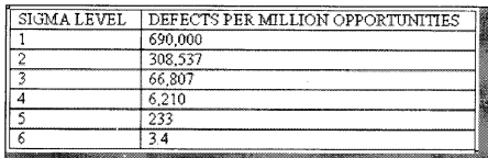
Therefore, I should only have 3.4 defects in a million defects then I can say I am six sigma.
Question 52.
What are DMAIC and DMADV?
Answer:
Six Sigma has two key methodologies DMAIC (Define, Measure, Analyze, Improve and Control) and DMADV (Define, Measure, Analyze, Design, Verify). DMAIC is used to improve an existing business process. DMADV is used to create new product designs or process designs in such a way that it results in a more predictable, mature, and defect-free performance.
DMAIC
Basic methodology consists of the following five phases:
- Define: formally define the process improvement goals that are consistent with customer demands and enterprise strategy.
- Measure: to define baseline measurements on the current process for future comparison. Map and measure the process in question and collect required process data.
- Analyze: to verify the relationship and causality of factors. What is the relationship? Are there other factors that have not been considered?
- Improve: to optimize the process based upon the analysis using techniques like the Design of experiments.
- Control: set up pilot runs to establish process capability, transition to production, and thereafter continuously measure the process and institute control mechanisms to ensure that variances are corrected before they result in defects.
DMADV
Basic methodology consists of the following five phases:
- Define: formally define the goals of the design activity that are consistent with customer demands and enterprise strategy.
- Measures: to identify CTQs (Critical to Quality), product capabilities, production process capability, risk assessment, etc.
- Analyze: to develops and design alternatives, create a high-level design, and evaluates design capability to select the best design.
- Design: to develop the detailed design, optimize design, and plan for design verification this phase may require simulations.
- Verify: to design, set up pilot runs, implement the production process, and hand over to process owners. This phase may also require simulations.
Question 53.
What are the various ways of doing software estimation?
Answer:
There are many techniques available for estimating a project:
- Function points
- Use Case points
- WBS, etc.
Question 54.
What is function point estimation?
Answer:
In function point, we break the application into smaller pieces called as elementary process and estimate the application.
Question 55.
How did you estimate by using function points?
Answer:
Below are the steps in function points:
• First Count ILF (Internal Logical File), EIF (External Interface File), El (External Input), EQ (External Inquiry), RET (Record Element Types), DET (Data Element Type), FTR (File Type Referenced) and use the rating tables. After you have counted all the elements, you will get the unadjusted function points.
• Put rating values 0 to 5 to all 14 GSC (General System Characteristic). Adding all total 14 GSC to come out with total VAF (Value Adjustment Factor). Formula for VAF = 0.65 + (sum of all GSC factor/100).
• Finally, make the calculation of the adjusted function point. Formula: Total function point = VAF * Unadjusted function point.
• Make an estimation of how many function points you will do per day. This is also called as “Performance factor”.
• On basis of performance factors, you can calculate Man/Days.
Question 56.
What is the FP per day in your current company?
Answer:
Left to the readers as every company has its own FP (Function Point) per Day. For .NET its 0.8 FP
per day as a general standard.
Note: There is a free PDF (Portable Document Format) provided “How to prepare Software Quotations?”
Please do refer Function point chapter.
Question 57.
What is SMC (System Management Controller) approach of estimation?
Answer:
In this approach, we divide the project into small sections and assign complexity factories (simple, medium, and complex) to each of those sections. Each of these complexities is assigned man-days and the total man-days are estimated.
Question 58.
How do you estimate maintenance projects and change requests?
Answer:
Most people use Simple, medium, and complex approaches for change request estimation.